Skip links

Technical information

AIR-COOLED HEAT SINKS

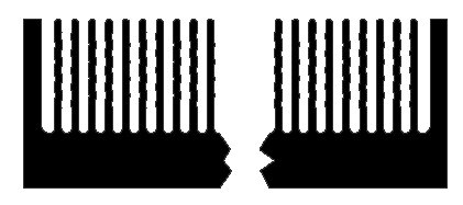
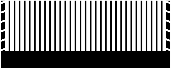
Material and mechanical processing

Lightness (2.7 g/cm³), thermal conductivity (120–229 W/m•K) and high workability are the main properties that make aluminium the ideal metal for manufacturing air-cooled heat sinks. 
Unless otherwise specified, the characteristics of the extruded profiles used are as follows:  

  • Chemical composition: Aluminium alloy EN AW-6060, 6061, 6063, 6101B or 6082, in accordance with European standard EN 573-3.  
  • Mechanical characteristics: T5 or T6, in accordance with European standard EN 755-2.  
  • Dimensional and shape tolerances according to European standard EN 755-9.  

Unless otherwise specified in the design, the products are machined in accordance with the general tolerances specified by ISO 2768-mK, maximum surface flatness 0.05/100 mm and maximum roughness Ra 1.6 µm. However, unless otherwise specified, parts that do not comply with the prescribed general tolerances shall not be automatically rejected when the functionality of the part is not compromised.  

How to choose a heat sink

The use of a heat sink in an electronic system, promoting heat transfer between the device and the environment, leads to a reduction in the thermal resistance of the entire system, allowing the temperature reached by the electronic device to be lowered for the same amount of power dissipated or, by exploiting the maximum operating temperature, to have a higher dissipatable power. The performance of a heat sink is measured by its thermal resistance RTH[K/W], which takes into account the transmission of heat by convection and radiation from the heat sink to the colder surrounding environment. The thermal resistance of a heat sink depends on several factors, such as the material used (thermal conductivity), shape and size, colour and surface finish (radiation efficiency and contact resistance), ventilation and mounting conditions (natural or forced convection). The lower the thermal resistance, the better the performance of a heat sink.

Knowing the ambient temperature TA, the maximum power dissipated by the device Pd and the maximum permissible temperature on the heat sink surface TMAX, the maximum thermal resistance value of the heat sink required by the design can be calculated as 

It is therefore necessary to choose a heat sink with a thermal resistance equal to or less than that calculated. 

Thermal resistance measurement conditions 

The products are presented in order of shape and size, expressed in millimetres. The following parameters are given for each profile:  

  • Kg/m: Weight in kilograms of the profile per unit of length (metre);  
  • L: Length in millimetres of the heat sink fixed for the calculation of the indicated thermal resistance. For different lengths, refer to the product data sheet downloadable from the website or to the ‘Length Correction Factor’ graph to calculate the multiplication factor to be applied to the indicated thermal resistance, both in natural and forced convection;  
  • W: Width in millimetres of the heat sink fixed for the calculation of the indicated thermal resistance (only for high-efficiency assembled heat sinks). As the width of the heat sink varies, the thermal resistance curve can be approximated linearly, and therefore by doubling the width of the heat sink, the thermal resistance is halved;  
  • RTH,N: Thermal resistance in natural convection expressed in K/W with a temperature rise of 70°C (ambient temperature 25°C);  
  • RTH,F: Thermal resistance in forced convection expressed in K/W with an air speed of 3 m/s and a temperature rise of 50°C (ambient temperature 25°C). For air flows at different speeds, refer to the ‘Air Speed Correction Factor’ graph to determine the multiplication factor to be applied to the indicated thermal resistance.  

For the Profilmecc and ProfilmeccPlus product lines, the forced convection thermal resistance curve is shown as the air flow varies for specific lengths.  

The thermal resistance values shown are derived from laboratory tests or software simulations under conditions similar to those encountered in reality.  
In particular:  

  • Heat source evenly distributed over approximately 50% of the mounting surface and located at the centre of the heat sink with silicone grease interposed;  
  • Temperature measured on the surface of the heat sink in the immediate vicinity of the heat source using low thermal inertia thermocouples;  
  • In natural convection, the heat sink is positioned for maximum efficiency with vertical fins. For horizontal mounting, an increase in RTH,N of approximately 20% should be considered;  
  • Untreated heat sink surface. For black anodised parts in natural convection, the thermal resistance value RTH,N should be reduced by approximately 10%.  

The technical data reported is derived from laboratory tests and simulations carried out accurately and is therefore to be considered reliable. However, as actual conditions of use may differ, it is advisable to carry out a practical check under the conditions in which the heat sink will be used.  

Ricerca avanzata

Trova subito il prodotto ideale
[wpdreams_ajaxsearchpro id=1]
Dissipatori raffreddati
AD ARIA
Piatti raffreddati
A LIQUIDO
Piastre e placche
ALplate