TECHNICAL INFORMATION
 MATERIAL AND MECHANICAL MACHINING
The lightness (2,7 g/cm3), the thermal conductivity (220 W/m*K) and the malleability are the main properties making aluminium the most suitable metal for our heat dissipation systems. If not otherwise stated, the characteristics of used extruded profiles are:
Chemistry composition: Aluminium Alloy EN AW-6060, 6061, 6063 or 6082, according to EN 573-3 European regulation
Mechanical characteristic: T5 or T6, according to EN 755-2 European regulation
Tolerances on dimensions and form according to EN755-9 European regulation
If not specified on drawing and agreed with customer, the heatsinks are machined according to general tolerances indicated on ISO 2768-mK international regulation. However, if not otherwise stated, not comply pieces to above general tolerances should not automatically be refused when their functionality is not compromised.
SPECIAL PRODUCTS
Mecc.Al manufactures and supplies the following mechanical supports for electronic industry:
Extruded commercial profiles (flat bars, angles, square bars, L and U profiles)
Extruded boxes and cases
Enclosures for high frequency technology made from a full aluminium profile
HOW TO SELECT A HEAT SINK
A heat sink in an electronic system, by enhancing the heat dissipation from the electronic device (hot surface) to the colder surrounding environment, allows to decrease the thermal resistance of the whole system and therefore the temperature achieved from by the device is lower. In the same way, by fixing the maximum device working temperature, a heat sink allows to dissipate a higher power.
The performance of a heat sink is related to its thermal resistance [K/W] provided by the manufacturer's datasheet, that takes in account of the convection and radiation heat transferring from the heat sink to the surrounding environment.
The thermal resistance depends on different factors: material (thermal conductivity), shape and size, colour and surface finishing (radiation efficiency and contact resistance), convection power and heat sink mounting position (natural or forced convection). Obviously, To a smaller thermal resistance corresponds a better heat sink performance.
By knowing the ambient temperature , the power to be dissipate from the electronic device , its junction to case thermal resistance and maximum allowable temperature , it is possible to calculate the maximum allowable heat sink thermal resistance value as

Where is the case to heat sink thermal resistance, depending on thermal resistivity of the material used on the case to heat sink interface within the interface case-heat sink for getting an homogeneous contact surface (usually, silicone grease).
Therefore it is necessary to select on the catalogue a heat sink having a thermal resistance value at least equal or less than the calculated one.
MEASUREMENT OF THERMAL RESISTANCE
In the catalogue, the heat sinks are shown divided for kind type of product and shape, in increasing order by size (in millimetres). For each profile, the following parameters are indicated:
Kg/mt: Profile weight (kilograms per meter)
L: Heat sink length in millimetres, fixed in order to calculate the shown thermal resistance
W: Heat sink width in millimetres, fixed in order to calculate the shown thermal resistance (only for HIGH PERFORMANCE heat sink)
RTH,N: Thermal resistance [K/W] in natural convection calculated with a at 70°C sink to ambient temperature difference (25°C ambient temperature)
RTH,F: Thermal resistance [K/W] in forced convection calculated with an air speed of at 3 m/s air speed and a 50°C sink to ambient temperature difference (25°C ambient temperature). For different air flow speed, refer to "AIR SPEED CORRECTION FACTOR" graph to calculate the multiplication factor to apply to the given thermal resistance.
For Profilmecc & ProfilmeccPlus and Brazed fins heat sink product lines, it's showed the thermal resistance in forced convection graph by varying the air flow at specific heat sink lengths.
The thermal resistance values come from tests made at Mecc.Al air conditioned laboratory with following conditions:
One heat source placed in the middle of the heat sink by using silicone grease between them
Heat source evenly distributed over approximately 50% of the mounting surface and placed in the middle of the heat sink through silicone grease within the interface
Temperature measured on the heat sink surface under the heat source through miniaturized thermocouples
In natural convection tests, fins are vertically arranged. In horizontal use, the thermal resistance value has to be increased by around 20%
Raw surface heat sink. For black anodized heat sink surface in natural convection, the thermal resistance value has to be decreased by around 10%
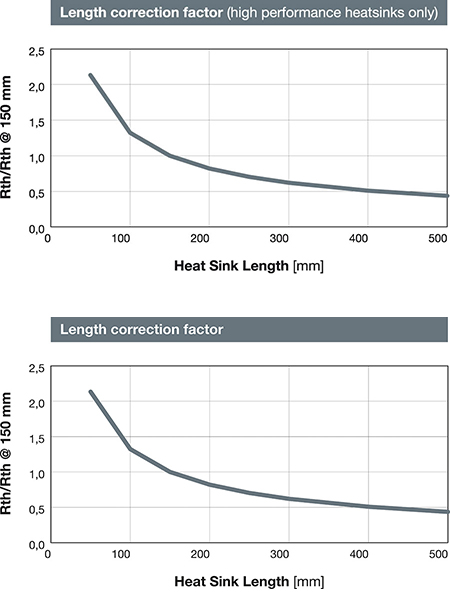
The thermal resistances values are related to the shown profile length. The thermal resistance decreases with a non-linear law by increasing the heat sink length. For assembled HIGH PERFORMANCE heat sinks, the thermal resistances have been calculated for a 150 mm long piece. For different lengths, it is necessary to multiply the given thermal resistance value by the appropriate factor provided from "LENGTH CORRECTION FACTOR" graph (for both natural and forced convection cooling).
The thermal resistance decreases with a non-linear law by increasing the heat sink length. The thermal resistances values are related to the indicated profile length; For different lengths, it is necessary to multiply the given thermal resistance value by the appropriate factor provided by "Length Correction Factor" graph, for both natural and forced convection cooling
For assembled High Performance heat sinks, the thermal resistances have been calculated for an around 100 mm wide piece (W). Varying the heat sink width, the thermal resistance curve value can be approximated with a linear law, that is by doubling the heat sink width, the thermal resistance is halved.
The technical data listed on this catalogue come from thermal simulations and laboratory tests run in an accurate way, so they can be considered reliable so that they have to be considered as reliable. However, taking into account that the heat sink working conditions of any customized application could be different from the laboratory ones, we suggest to run perform a thermal test with the same final customer application conditions.